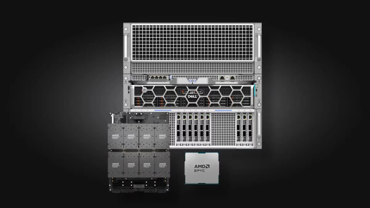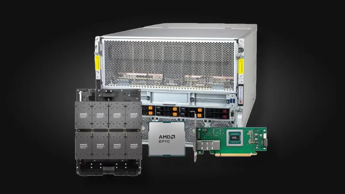
AMD powers the world’s leading scientific computing, from the exascale supercomputers driving discovery in the United States and Europe to Lux, the first Genesis Mission system for AI-driven science. With leadership CPUs, GPUs, FPGAs, networking and the ROCm™ software, AMD gives nations, laboratories and enterprises a single open platform for high-performance computing, AI for science, sovereign AI, agentic AI and the path to quantum computing. On that path, the first place quantum and classical computing must work as one is error correction.
Fault-tolerant quantum computing depends on a classical feedback loop that keeps up with the qubits: measurement data has to reach classical compute, be decoded, and come back as a correction in time. AMD and Qblox are building that loop together. Qblox provides the control stack: the Cluster, a modular rack of synchronized control and readout modules whose Q1 sequencers run the experiment, linked by the LINQ feedback network and kept in lockstep by SYNQ. AMD brings everything past it: the Adaptive SoCs and FPGAs, Instinct™ GPUs and EPYC™ Server CPUs. On its way, the loop crosses two boundaries. The first is inside the control stack, where FPGA-based modules coordinate circuit executions, and qubits read out. The second is between the control stack and the classical compute fabric that computes the quantum error correction algorithms.
Figure 1: A quantum processor, its control system, and AMD classical compute CPUs, GPUs, and FPGAs exchanging syndromes and corrections
This post is about the second boundary and provides answers to two aspects. First, we build a direct interconnect between the control system and any accelerator’s memory with as little latency as the hardware allows. Second, we demonstrate an execution model in which several programming models (Python, C, OpenMP, chains of GPU kernels) can serve the loop side by side and interoperate in real time, so that the code answering a measurement can come from anywhere rather than something only one framework can run. The rest of the post takes them in that order: the interconnect we built, then the runtime that provides that execution model.
A loop with four kinds of processor
Real-time quantum error correction has to measure, decode and correct inside the coherence window. The control system cannot wait for an answer indefinitely: The quantum program may continue while QEC data is decoded. The decoder’s result must be ready before the first operation or measurement interpretation that depends on it; that is what “in time” means here.
One error-correction round looks like this:
- The control system publishes syndrome measurements.
- A link card writes them into a queue in an accelerator’s memory.
- Code on the accelerator decodes them.
- The correction returns.
- The control program continues with the correction applied.
Decoding is a reason the loop has to be fast and devices must interoperate at low latency. However, other parts of the program, or the system, will benefit from low latency such as calibration, telemetry, control elements (tracking drift, adaptive measurement, active-reset decisions), and the classical compute steps of the whole application. The further you move from decoding, the less that code is a fixed function and the more it is ordinary software: written in existing languages, calling existing libraries, built with existing programming models. Although we focus on the decoding case in this post, the path we build serves the others equally.
That makes the outer loop, control and classical compute, a heterogeneous-computing problem. Decoders have already been built for FPGAs, CPUs and GPUs, and the calibration and application code that follows will have the same range of choices; where each piece runs best is still an open question. Until it settles, the interconnect should not pick a winner: a control FPGA, GPUs, CPUs and adaptive SoCs should all be able to sit on the same loop. So we separate three concerns, each replaceable on its own: what physically carries the bits (the physical link), how devices hand each other work and replies (what we call the exchange layer), and what computes (the runtime). We start with the interconnect.
Figure 2: Compute, exchange, wire. AMD Instinct GPUs, AMD EPYC CPUs and AMD Versal adaptive SoCs sit on one exchange layer in device memory; the physical link below it is replaceable, and the slot marked + is open for future IP.
The interconnect we built: from an Aurora cable into accelerator memory
From the cable to accelerator memory
Figure 3: The interconnect we built. An Aurora link carries frames from the control system to an AMD Alveo™ U55C link card, which lands each request directly in accelerator memory over PCIe and sends the reply back the same way.
The control system connects to an AMD Alveo™ U55C link card over Aurora 64B/66B, AMD’s lightweight point-to-point serial protocol: four lanes at 10.3125 Gb/s each, lossless and in order, with flow control carried in band. Inside the card, the Aurora plug-in hands whole frames to a bridge core as 512-bit words at 250 MHz. An exchange-layer engine then writes each request straight into a queue in the accelerator’s memory with posted PCIe peer-to-peer writes. After the sequence word with the last marker, the exchange layer watches a reply queue in the FPGAs own memory, which the accelerator fills with posted writes. No software on the host touches a frame. Notice that the requests queue is strategically placed on the accelerator’s memory, while the reply queue is placed inside the FPGA. This is to facilitate the polling mechanism on each side.
The interconnect itself is cheap. Across the cable and both cards’ link stages, a frame and its reply spend 0.44 µs; landing a request in accelerator memory takes 10 ns, reading the reply out of card memory 40 ns, and sending it back 30 ns: about half a microsecond in all.¹ The rest of a round trip is the accelerator noticing the request, computing, and publishing its answer, which is where the next round of work goes.
Using the Aurora phy link is not mandatory. The Aurora plug-in sits behind a contract of its own: deliver whole frames, losslessly and in order, and count every error. Nothing above it is Aurora-specific, so another serial protocol that honors the contract drops in without touching the engine, the queues or the runtime. This link runs between the control system and the accelerator host; it is not the serial fabric between control modules inside the control stack, the first boundary.
Two queues, publish last
The exchange layer is two queues:
- a request queue in the consumer’s memory, where the producer writes a slot and then a sequence word, last;
- a reply queue in the producer’s memory, where the consumer writes the reply, issues a release fence, and then a ready word, last.
Figure 4: How a message is formed. In the classic encoding the data comes first and one word, written last, publishes it; a reply adds a release fence before its ready word. In the per-piece encoding every 16-byte piece carries the message's sequence number, so each piece is self-validating.
Each side polls only its own memory, so the hot path never reads across PCIe. The published word is the doorbell, and it travels with the payload in both directions. Because measurement payloads are only a few bytes, they fit alongside the doorbell, which saves a separate fetch of the data and its round trip. A slot is reused only after its reply has been consumed. The release fence is what makes the ready word trustworthy: without it, the card could see the ready word ahead of the reply's bytes. Each consumer keeps that guarantee in the cheapest way it can: a fence on a GPU or CPU, PCIe's own write ordering on the V80, and, in the second encoding below, no publish word at all.
The queues also come in a second encoding, for consumers that benefit from it. Instead of one publish word per message, every 16-byte piece of the message carries the message's sequence number, so the reader can trust each piece the moment it arrives, with no separate publish word and no fence after the data. Today the GPUs use it in both directions for the runtime's built-in echo, which is what the latency figures below measure, as does the EPYC 7282 CPU at 64 bytes; sessions that serve user functions still use the classic encoding.²
Three swap tests show the separation holds. Change the physical path and the consumer does not change: the GPU kernel never knows which link delivered a frame. Change the consumer and the producer does not change: making a CPU consume the card’s loop needed no change to the card’s logic, its image, the driver or the ABI, and the same card image also served an adaptive SoC. And, as the next section shows, change the programming model and both ends stay the same.
The host only sets up
The host's job ends before the first frame arrives. At session start it links the runtime and your functions into the persistent kernel, allocates the request and reply queues and pins them in device memory, and maps each queue so its peer can write into it directly over PCIe. It then programs the link card with the queues' addresses, launches the persistent kernel and steps back. From then on the frame path involves only the devices. The card writes each request straight into the accelerator's memory; the accelerator, polling its own memory, finds it, answers it and writes the reply straight into the card's memory; and the card, polling its own memory, picks the reply up. No interrupt, driver call or host thread touches a frame, so for inline functions no host call is on the frame path.
To test this, we froze the host process in the middle of a run, stopping every one of its threads, while the card kept sending requests and checking every reply. The GPU and the V80 kept answering throughout the freeze, with no verification failures, and the run continued normally once the process was resumed.² A CPU consumer is the exception by construction, since its consumer is a host thread. However, one can build a runtime that separates threads that communicate from others that do work. The OpenMP and chain paths described in the next section also keep host roles of their own: another runtime launches the OpenMP region, and a host thread re-arms a kernel chain.
Logic on the same exchange layer
An AMD Alveo™ V80 Compute Accelerator meets the same exchange layer in programmable logic: it claims requests, checks them, and writes replies with the publish word last, with no PCIe read on either card. Our experiments use small lookup decoders for the Steane-7 and repetition-3 codes that return logical errors equal to the ground truth.² Logic joins the loop next to GPUs and CPUs because the seam is in memory, not in host software.
In these measurements only the exchange logic runs on the V80, without the rest of a circuit behind it, so it also shows what the system costs on its own. Its logic answers 28 ns after it sees a request, yet its round trip is 2.43 µs (median): almost all of it is the platform. The request crosses PCIe from the link card into the V80, the reply crosses back into the card’s memory, and the card notices it. The V80 orders each reply behind its data using the order in which PCIe delivers posted writes, so it never waits for a write acknowledgement.²
The interconnect gets every request into accelerator memory, and every reply back, without the host. What answers those requests, and in which programming model, is the other half of the design.
Where the seam sits
In our design, the seam between devices is not a host-side software interface. It is a contract in device memory: a layout of bytes and the rules governing when they can be read and written. A host-side interface separates software from the transport, but each device still depends on a host library in its path. A memory contract, by contrast, separates the devices themselves. Anything that reads and writes the bytes in the specified order can participate—whether it is a GPU kernel, a CPU thread, or a block of logic. The same specification can generate definitions for C, Python, and SystemVerilog, allowing software and hardware to implement over a single shared contract.
The runtime is a library
Composing software on accelerators has always been hard: every library and programming model brings its own runtime, queues and assumptions about who owns the device. We refer to this issue as the “Too many chefs in the kitchen” problem of runtimes. Its solution is to create program execution models that are separate from a specific programming model or programming languages. Real time on Quantum computers adds another layer of complexity to the equation.
- The work starts at the qubit, not at the host. Streams, graphs and OpenMP target regions assume a host-centric view where a CPU program launches the work. Here a device triggers it, so the usual offload model runs backwards, and real-time and near-time work live on different timescales.
- Composition must not cost time. An extra launch or synchronisation is noise in ordinary offload. In the loop it eats into the deadline.
- The device never stops running. A persistent kernel occupies the GPU, so libraries and other programming models have to coexist with it instead of taking turns.
So the QPU runtime cannot own main(). Rather than a framework that owns the program, we built a framework-agnostic device runtime that goes wherever your code already runs, and that your existing tools can host. Your application can be a Python function, a C function or an LLVM OpenMP target region. All three are clients of one library, and they give identical answers.³
Therefore, we must emphasize that this work is not a proposal for a Python interface. It is about how to make software composable in real time, and our answer is a library underneath every interface. The code in this post comes from a research prototype: its names and syntax, especially the Python front end, are not a fixed interface. What we argue for is the library’s design; the front ends on top can change, or be replaced by an existing framework’s, without changing it.
The library underneath
The device runtime library is one freestanding C header. This is used in architectures that lack the logic to communicate (i.e., the GPU and the CPU in our examples). To allow direct integration with the application via JIT, the library is compiled to LLVM bitcode for AMD GPUs and natively for the host, and four design properties make composition possible:
- A small set of verbs. A consumer claims work with next and returns it with complete; it reads the request and appends the reply; and it composes with other kernels through signals, device-side queues and graphs. Any code that can call these verbs can serve the loop.
- An ABI any front end can target. Every call takes and returns only scalars and pointers, so the declarations are identical for the GPU and the host, and a front end that emits LLVM IR needs no per-target lowering. That is what makes Python, C and OpenMP equal citizens.
- Memory ordering lives only inside the library. No client writes a fence. The hardest real-time correctness problem, publishing a reply only after its bytes are visible, is solved once rather than by every client.
- One target layer, one byte specification. Wave size and lane id come from a per-target layer, never from a constant, and shared types are generated from one specification so that separately built kernels agree.
Excerpt of the device runtime library’s header (prototype names). This is the part we argue for; everything else in this post is a client of these calls. The prototype calls the functions it serves “handlers”, hence handler_id; in this post we just call them functions.
The pattern will look familiar to anyone who has worked on LLVM’s OpenMP device runtime: per-target code behind one interface, shipped as bitcode and linked late.
Inserted into the kernels we JIT
A key aspect of achieving low latency, is to make sure the kernel that contains the runtime control logic, is the same that executes the code. In the presence of multiple functions (i.e., handler_ids), the runtime must generate a single kernel that inlines the functionality of all possible kernels. When a session starts, the library, your functions and a generated dispatch table are linked into one persistent kernel: there is no launch per frame and no host call. That is how composition avoids costing time. The link is a one-time cost at session start: about 29 ms when the linked image is cached and 4.8 s when it is not.³
For external kernels, we explore device-to-device dispatches via traditional mechanisms. For the MI210 GPU, for example, we use HSA queues that allow the persistent control kernel to dispatch a second kernel.
An advantage of working at the LLVM-IR level, and using JIT, is that we can directly access the libc implementation for the GPU (as well as other libraries), as supported by the upstream repository. Thus, this gives math.h support out of the box for kernel generation.
GPU Clients: front ends and programming models
In our prototype, the runtime can host a function in four ways: ① inline (linked into the library’s persistent kernel), ② resident worker (a separate persistent kernel that takes work from a device-side queue), ③ external (another programming model owns the kernel and calls next and complete) or ④ kernel chain (ordinary kernels, pre-armed in an HSA queue, that the persistent kernel releases with one store and whose completion signal triggers the reply). The first three are clients of the library; a chain’s kernels need not know the loop exists. The control side never knows which one answered.
Figure 5: Four ways to host a function. Inline functions ① run inside the control kernel. Otherwise the kernel hands the frame on: through a task queue to a resident worker ②, through an endpoint queue to an OpenMP region ③, or, with a single store, to a chain of ordinary kernels ④ pre-armed in an HSA queue.
A Python front end is one possible client, served inline ①. It lowers straight to LLVM IR that calls the library; inputs bind by name to the values the control program publishes, and the return value fills the reply the control program waits for.
Listing 1: One possible front end (prototype syntax). b is the corpus’s second input, used by its two-argument functions. math.sin here is not Python’s: it lowers to LLVM’s libm for the GPU. This example shows numerical code with library calls that shape a calibration step.
On the card path, the card checked every one of this function’s 3 × 10⁶ replies against the host’s result without a mismatch. Its round trip is 6.33 µs (median): a session that serves user functions currently takes the runtime’s general path, not the fast path that serves the built-in echo in Figures 7 and 8.³
Following with a different example, LLVM’s OpenMP offloading is an external client ③. LLVM’s ompx_bare extension launches a target region as a plain kernel with a fixed grid; inside it, the region uses the library’s verbs to consume the frames addressed to one function:
Listing 2: An OpenMP region as a client (condensed; prototype names). qod_next and qod_complete_rc are the whole contract between a programming model and the runtime. We measured the region both ways: on its own, it claims and routes frames itself inside next; alongside the runtime’s control kernel, the control kernel routes for it.
The library routes each frame, by the function it is addressed to, to its own endpoint queue, one consumer per endpoint; two endpoints served by two OpenMP teams each seeing only the frames addressed to their own function.⁴ On AMD GPUs the native route to device-initiated work is the HSA queue, the GPU’s own dispatch packets: the host arms a chain of ordinary kernels ④, and a single store into GPU memory releases it. Such a mechanism could be a building block for supporting HipGraphs. The trigger reaches the first kernel in 1.92 µs (median).⁴ A host thread still re-arms the chain by default, and 0.37–0.93 % of frames wait for it.³
Composition works, but it is not free yet. On the card path, a chain ④ publishes its answer 1.2 µs later than a resident worker ② running the same body, and an OpenMP region ③ costs 6.5 µs more than the same decoder inlined ① when it routes for itself, and 4.4 µs more when the control kernel routes for it, at both 64 and 1,792 bytes, with identical replies; all are medians.³
Alongside the libraries you already use
LLVM’s libc and libm for GPUs are linked in beside the runtime at session start, and the runtime hosts libc’s RPC server. A QPU endpoint turns out to be the same device-to-host ring pattern libc already uses, with an FPGA as the peer. Every math function the target supports, lowered from Python to libm, agrees with the host’s results in our test on the AMD Instinct MI210, and C functions call sin() and printf() from inside the persistent kernel (printf goes through the host and is for debugging).⁴ On the card path, sin() called from C stayed within 1 ulp of the host’s on every round, and every printf line arrived.³
GPUs and CPUs, one library
The same library is built for AMD Instinct GPUs and natively for CPU cores, and a function moves between them by naming another device.
Figure 6: One library, many clients. Python, C, OpenMP regions, resident workers and kernel chains all reduce to calls into the device runtime library, which is built for AMD Instinct GPUs and for CPU cores. LLVM libc and libm sit alongside it. The numbers mark the four ways to host a function: ① inline, ② resident worker, ③ external and ④ kernel chain.
What we measured
The results in this section are U55C-to-device round trips: each starts when a request enters the AMD Alveo™ U55C high performance compute card and ends when the card has the reply, so they cover the link card, PCIe and the accelerator, but not the control system or the cable to it. All loop numbers are closed-loop round trips, one request in flight, over 3 x 10⁶ rounds per configuration. They are timed on the link card’s 250 MHz clock from boundary to boundary, with every ordering and checking guarantee included. Every consumer runs at its shipped default settings and answers with the runtime’s built-in echo function.²
Image Zoom
Figure 7: Round-trip latency with 64-byte frames, on the AMD EPYC 7282 host (top) and on the second platform, an AMD EPYC 9755 host (bottom). The bars show individually logged rounds at the clock’s 4 ns resolution. On the V80 only the exchange logic is in the loop. On the MI355X, p50 and p90 fall in the same histogram bucket, so its two lines coincide.²,⁵
Consumer (64-byte frames)
p50
p90
AMD Alveo™ V80 Compute Accelerator
2.428 µs
2.492 µs
AMD EPYC™ 7282 CPU, one core
2.172 µs
2.268 µs
AMD Instinct™ MI210 GPU
3.708 µs
3.804 µs
AMD EPYC™ 9755 CPU, one core (second platform⁵)
1.772 µs
1.820 µs
AMD Instinct™ MI355X GPU(second platform⁵)
3.036 µs
3.036 µs
All five are tight: on every consumer, 90 % of rounds finish within 0.10 µs of the median. For a function this small, one CPU core answers sooner than a GPU; a GPU earns its place when the function is real compute.
The histograms in Figure 7 show a few sharp spikes because, in these runs, the control traffic is simulated on the link card’s own FPGA, on the same clock that times it, and each request leaves the moment the previous reply lands, so every round starts at the same point in the consumer’s polling cycle; the Qblox Cluster runs later in this post, across a cable from an independent clock, spread smoothly instead.
The results carry over to a second, newer platform: an AMD EPYC™ 9755 host with an AMD Instinct MI355X GPU and the same link card. At its defaults, the MI355X answers in 3.036 µs at 64 bytes (p50 and p90 alike), 0.67 µs sooner than the MI210; one EPYC™ 9755 core answers in 1.772 µs (p90 1.820 µs). The V80 was not part of this platform.⁵
Image Zoom
Qblox Cluster meets AMD
From pairs to a mesh
Conclusion
Footnotes